Pre-Molded (PM) Series Cold Shrink Accessories
As a cable accessories manufacturer, we offers a range of cable accessories to meet medium voltage, high voltage, ultra high voltage and extra high voltage requirements.The Pre-Molded (PM) series of cold shrink medium voltage cable accessories are high-end products available for extruded dielectric power cables from 8.7kV through 35kV and up to 630mm2.
State-of-the-art software is employed to perform electric stress analysis and optimization which ensures the electric stress of these cable accessories is distributed in the most rational way. Liquid silicone rubber is used as the raw material, which greatly improves the mechanical and electrical properties of this product. This allows installation in various kinds of complicated environments, resulting in simple, reliable installation and excellent product performance.
Features and Benefits
- • Liquid silicone rubber (LSR) is used for outstanding electrical conductivity and insulation
- • Employs design concepts used for high voltage stress control
- • Hydrophobic and highly UV resistant for excellent performance in outdoor applications
- • Superior flexibility ensures that the product holds the cable firmly, eliminating air gaps produced by thermal expansion and contraction during operation
- • With 300% expansion allowance, a single product can be used with a variety of cable sizes
- • Does not require special skills when installing
- • Eliminates uneven heating that may occur when installing heat shrink accessories
- • Single piece pre-molded design eliminates errors that could occur with multiple piece accessories
Applications and Standards
- • Standard and non-standard cables with extruded solid insulation (XLPE and EPR)
- • Copper and aluminum conductors
- • Metal shielding (Copper Wire, Copper Tape, AluminumFoil, etc.)
- • Armored or non-armored jackets (Steel wire armor,etc.)
- • GB/T 12706
- • GB/T 18889
- • IEC 60502
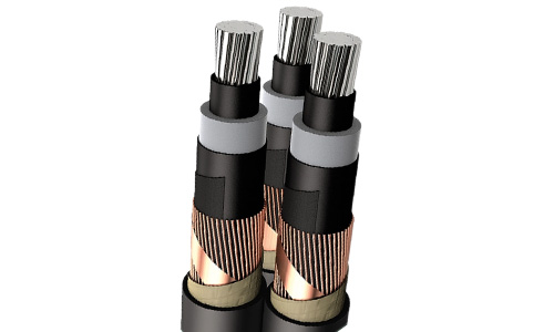
Three-core Power Cable with Extruded Insulation Applications

Three-core Power Cable with Extruded Insulation Indoor/Outdoor Terminations
| Main Parameters | 8.7/15kV | 12/20kV | 26/35kV |
| AC power frequency withstand voltage (5 min.) | 39kV | 54kV | 117kV |
| Power frequency withstand voltage (1 min., wet, outdoor terminals only) | 35kV | 48kV | 104kV |
| DC withstand voltage (15 min.) | 35kV | 48kV | 104kV |
| Impulse voltage test (+/-10 times) | 95kV | 125kV | 200kV |
| Partial discharge test | ≤10 pC at 15kV | ≤10 pC at 20kV | ≤10 pC at 45kV |
| Combined cycling test with AC voltage, 60 cycles (In air) |
23kV | 30kV | 65kV |
| Salt spray test (Outdoor) | 11kV | 15kV | 33kV |
| Wet aging test (Indoor) | 11kV | 15kV | 33kV |
Three-core Power Cable with Extruded Insulation Indoor/Outdoor Termination Kit

| Voltage Class, kV | Conductor Cross Section, mm2 |
Indoor Termination Type Chart | Outdoor Termination Type Chart | ||
| Single-Core Kits | Three-Core Kits | Single-Core Kits | Three-Core Kits | ||
| 8.7/15kV |
25-50 | PMN15-1.1 | PMN15-3.1 | PMT15-1.1 | PMT15-3.1 |
| 70-120 | PMN15-1.2 | PMN15-3.2 | PMT15-1.2 | PMT15-3.2 | |
| 150-240 | PMN15-1.3 | PMN15-3.3 | PMT15-1.3 | PMT15-3.3 | |
| 300-400 | PMN15-1.4 | PMN15-3.4 | PMT15-1.4 | PMT15-3.4 | |
| 500-630 | PMN15-1.5 | PMN15-3.5 | PMT15-1.5 | PMT15-3.5 | |
| 12/20kV |
30-50 | PMN20-1.1 | PMN20-3.1 | PMT20-1.1 | PMT20-3.1 |
| 70-150 | PMN20-1.2 | PMN20-3.2 | PMT20-1.2 | PMT20-3.2 | |
| 185-400 | PMN20-1.3 | PMN20-3.3 | PMT20-1.3 | PMT20-3.3 | |
| 500-630 | PMN20-1.4 | PMN20-3.4 | PMT20-1.4 | PMT20-3.4 | |
| 26/35kV |
50-95 | PMN35-1.1 | PMN35-3.1 | PMT35-1.1 | PMT35-3.1 |
| 120-185 | PMN35-1.2 | PMN35-3.2 | PMT35-1.2 | PMT35-3.2 | |
| 240-400 | PMN35-1.3 | PMN35-3.3 | PMT35-1.3 | PMT35-3.3 | |
| 500-630 | PMN35-1.4 | PMN35-3.4 | PMT35-1.4 | PMT35-3.4 | |
Three-core Power Cable with Extruded Insulation Straight Joint Kits
| Voltage Class, kV | Conductor Cross Section, mm2 |
Straight Though Joint Type Chart | |
| Single-Core Kits | Three-Core Kits | ||
| 8.7/15kV |
25-50 | PMJ15-1.1 | PMJ15-3.1 |
| 70-120 | PMJ15-1.2 | PMJ15-3.2 | |
| 150-240 | PMJ15-1.3 | PMJ15-3.3 | |
| 300-400 | PMJ15-1.4 | PMJ15-3.4 | |
| 500-630 | PMJ15-1.5 | PMJ15-4.5 | |
| 12/20kV |
30-50 | PMJ20-1.1 | PMJ20-3.1 |
| 70-150 | PMJ20-1.2 | PMJ20-3.2 | |
| 185-400 | PMJ20-1.3 | PMJ20-3.3 | |
| 185-400 | PMJ20-1.4 | PMJ20-3.4 | |
| 26/35kV |
50-95 | PMJ35-1.1 | PMJ35-3.1 |
| 120-185 | PMJ35-1.2 | PMJ35-3.2 | |
| 240-400 | PMJ35-1.3 | PMJ35-3.3 | |
| 500-630 | PMJ35-1.4 | PMJ35-3.4 | |
| Main Parameters | 8.7/15kV | 12/20kV | 26/35kV |
| AC power frequency withstand voltage (5 min.) | 39kV | 54kV | 117kV |
| DC withstand voltage (15 min.) | 35kV | 48kV | 104kV |
| Impulse voltage test (+/-10 times) | 95kV | 125kV | 200kV |
| Partial discharge test | ≤10 pC at 15kV | ≤10 pC at 20kV | ≤10 pC at 45kV |
| Combined cycling test with AC voltage (30 cycles in air and 30 cycles in water) | 23kV | 30kV | 65kV |
Shielded Separable Connectors
Main Features1. High temperature vulcanized liquid silicone rubber is used for:
- Outstanding electrical performance
- Superior flexibility
- High weather resistance
- High aging resistance
- Flame retardant
2. Prefrabicated integrated design with built-in stress cone
3. Extruded outer shield with a considerable thickness
4. Attractive and lightweight, easy to install
5. Insulation plug with built-in voltage detector
6. Scalable connections allowing combinations
Applicable Standards
- • GB/T 12706
- • GB/T 18889
- • IEC 60502
- • EN 50180
- • EN 50181
Voltage Class, kV |
Conductor Cross Section, mm2 |
Shielded T Connector Type Chart | Shielded Rear Connector Type Chart | ||
| Single-core Models | Three-Ccre Models | Single-core Models | Three-Ccre Models | ||
| 8.7/15kV |
25-50 | PMTC15-1.1 | PMTC15-3.1 | PMBC15-1.1 | PMBC15-3.1 |
| 70-120 | PMTC15-1.2 | PMTC15-3.2 | PMBC15-1.2 | PMBC15-3.2 | |
| 150-240 | PMTC15-1.3 | PMTC15-3.3 | PMBC15-1.3 | PMBC15-3.3 | |
| 300-400 | PMTC15-1.4 | PMTC15-3.4 | PMBC15-1.4 | PMBC15-3.4 | |
| 500-630 | PMTC15-1.5 | PMTC15-3.5 | PMBC15-1.5 | PMBC15-3.5 | |
| 12/20kV |
25-35 | PMTC20-1.1 | PMTC20-3.1 | PMBC20-1.1 | PMBC20-3.1 |
| 50-70 | PMTC20-1.2 | PMTC20-3.2 | PMBC20-1.2 | PMBC20-3.2 | |
| 95-185 | PMTC20-1.3 | PMTC20-3.3 | PMBC20-1.3 | PMBC20-3.3 | |
| 240-300 | PMTC20-1.4 | PMTC20-3.4 | PMBC20-1.4 | PMBC20-3.4 | |
| 400-500 | PMTC20-1.5 | PMTC20-3.5 | PMBC20-1.5 | PMBC20-3.5 | |
| 26/35kV |
50-95 | PMN35-1.1 | PMTC35-3.1 | PMBC35-1.1 | PMBC35-3.1 |
| 120-185 | PMN35-1.2 | PMTC35-3.2 | PMBC35-1.2 | PMBC35-3.2 | |
| 240-300 | PMN35-1.3 | PMTC35-3.3 | PMBC35-1.3 | PMBC35-3.3 | |
| 400-500 | PMN35-1.4 | PMTC35-3.4 | PMBC35-1.4 | PMBC35-3.4 | |
Shielded T and Shielded Rear Connectors Kits
| Main Parameters | 8.7/15kV | 12/20kV | 26/35kV |
| AC power frequency withstand voltage (5 min.) | 35kV | 54kV | 117kV |
| DC withstand voltage (15 min.) | 39kV | 48kV | 104kV |
| Impulse voltage test (+/-10 times) | 95kV | 125kV | 200kV |
| Partial discharge test | ≤10 pC at 15kV | ≤10 pC at 20kV | ≤10 pC at 45kV |
| Combined cycling test with AC voltage, 63 cycles (33 in air + 30 in water) | 23kV | 30kV | 65kV |
| Shield resistance | ≤5 k Ω | ≤5 k Ω | ≤5 k Ω |
| Leakage current (at Um) | ≤0.5mA | ≤0.5mA | ≤0.5mA |
Shielded Rear Surge Arreste
| Name | Units | Parameters | |
| Product Model | _ |
PMBA15 (17/45) | PMBA20 (34/85) |
| System nominal voltage | kV | 10 | 20 |
| Surge protector rated voltage | kV | 17 | 34 |
| Continuous operating voltage | kV | 13.6 | 27.2 |
| Nominal discharge current, In | kA | 5 | 5 |
| Reference voltage, DC, 1 mA | kV | ≥24 | ≥48 |
| Leakage current, 0.75U, 1 mA | μ A | ≤10 | ≤10 |
| Steep current impulse residual voltage | kV | ≤51.8 | ≤95 |
| Lightning impulse residual voltage | kV | ≤45 | ≤85 |
| Switching impulse residual voltage | kV | ≤35 | ≤75 |
| Resistive current (Peak value) | μ A | ≤200 | ≤200 |
| Full current (Peak value) | μ A | ≤700 | ≤200 |
| Partial discharge at 14.3 kV | pC | ≤10 | ≤10 |
| 2ms square wave current impulse withstand | A | 200 | 200 |
| High current impulse withstand | kA | 65 | 80 |
250 A Euro Style Shielded Elbow Connector
Voltage Class, kV |
Conductor Cross Section mm2 | Shielded Elbow Connector | |
| Single-Core Models | Three-Core Models | ||
| 8.7/1.5kV |
25-50 | PMEC15250-1.1 | PMEC 152003.1 |
| 70-95 | PMEC15250-1.2 | PMEC 152003.2 | |
| 120 | PMEC15250-1.3 | PMEC 152003.3 | |
200 A American Style Shielded Elbow Connector
Voltage Class, kV |
Conductor Cross Section mm2 | Shielded Elbow Connector | |
| Single-Core Models | Three-Core Models | ||
| 8.3/14.4kV |
35-50 | PMEC15200-1.1 | PMEC 152003.1 |
| 70 | PMEC15250-1.2 | PMEC 152003.2 | |
| 95-120 | PMEC15250-1.3 | PMEC 152003.3 | |
| 150 | PMEC15200-1.4 | PMEC 152003.4 | |
Inner Cone Plug-in Separable Connectors
| Main Parameters | 12/20kV | 26/35kV |
| AC power frequency withstand voltage (5 min.) | 54kV | 117kV |
| DC withstand voltage (15 min.) | 48kV | 104kV |
| Impulse voltage test (+/-10 times) | 125kV | 200kV |
| Partial discharge test | ≤10 pC at 20kV | ≤10 pC at 45 kV |
| Combined cycling test at constant pressure, 63 cycles (33 in air + 30 in water) | 30kV | 65kV |

| Voltage Class, kV | Conductor Cross Section, mm | Single-Core Models | Three-Core Models |
| 26/35kV |
25 | GIS 35-1.1 | GIS 35-3.1 |
| 35 | GIS 35-1.2 | GIS 35-3.2 | |
| 50 | GIS 35-1.3 | GIS 35-3.3 | |
| 70 | GIS 35-1.4 | GIS 35-3.4 | |
| 95 | GIS 35-1.5 | GIS 35-3.5 | |
| 120 | GIS 35-1.6 | GIS 35-3.6 | |
| 150 | GIS 35-1.7 | GIS 35-3.7 | |
| 185 | GIS 35-1.8 | GIS 35-3.8 | |
| 240 | GIS 35-1.9 | GIS 35-3.19 | |
| 300 | GIS 35-1.10 | GIS 35-3.10 | |
| 400 | GIS 35-1.11 | GIS 35-3.11 | |
| 500 | GIS 35-1.12 | GIS 35-3.12 | |
| 630 | GIS 35-1.13 | GIS 35-3.13 |

